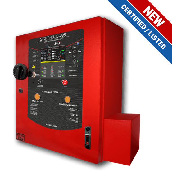
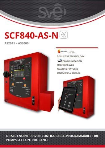
SCF840-D-AS control panels are high-specification, automatic, and configurable instruments engineered for efficiently managing the operations of diesel engine-driven fire-fighting pumpsets of any power in various environments.
They govern the start and stop of the diesel engine driven fire-fighting pumpsets and protect them by means of the action of the connected and controller-generated alarms, visualise the most relevant values and informations, and manage the communication with the operator and both the contour elements and the remote manned centre.
No | STANDARDS & TECHNICAL RULES |
---|---|
1 | Standard NFPA20 Ed.2019 |
2 | Standard NFPA70 |
3 | Standard IEC 61439-1 Ed. 2011 Low-voltage switchgear and controlgear assemblies |
5 | EMC: EN50130-4:2011 / IEC 62599-2:2010 / EN61000-6-3:2007 |
5 | Electrical safety:EN61010-1:2011 |
No | RANGE OF PRODUCTS (according to type plate) | |
---|---|---|
1 | Nominal supply voltage | 110Vac – 230 Vac (Consult other voltages) |
2 | Nominal frequency | 50Hz / 60Hz |
PANEL MODELS ACCORDING TO BATTERY CHARGERS | SCF840-D-AS 12070 | SCF840-D-AS 12100 | SCF840-D-AS 24050 | SCF840-D-AS 24100 |
Nominal Voltage | 12 V DC | 21 V DC | 24 V DC | 24 V DC |
Nominal Amps | 7 A | 100 A | 5 A | 10 A |
DIN Power | 96,6 W | 138,0 W | 138,0 W | 276,0 W |
Batteries capacity (C10) | 200 Ah | 285 Ah | 145,5 Ah | 285 Ah |
No | CONSTRUCTIVE FEATURES | |
---|---|---|
1 | CE marking: EMC | EN50130-4:2011 / IEC 62599-2:2010 / EN61000-6-3:2007 |
2 | CE marking; Electrical safety | EN61010-1:2011 |
3 | Enclosure | Ingress protection rating according to EN 60529:2018: IP65 |
4 | Protection against impacts degree according to EN60068-2-75:2014: IK10 | |
5 | Fireproof degree: The fire is extinguished in < 30s with dripping | |
6 | Display | TFT full colour 3,5″ 480×272 px |
7 | Cabling | Free of halogens |
8 | Fire resistance: RZ1 according to EN50200 (Max: 830º / 90min) | |
9 | Working temperatures | From -5ºC to 40ºC |
10 | Relative humidity (without condensation) | Functional from 20 to 95%. |
11 | Cooling | Natural convection |
12 | Maximum altitude | 2000m |
13 | Degree of contamination | 2 |
14 | Overvoltage category | II |
15 | Environment | CEM-I |
16 | Anti-vibration protection | EN60068-2-6:2008 |
No | MEASURING INSTRUMENTS IN THE DISPLAY | |
---|---|---|
1 | Batteries | 2 Voltmeter: Battery voltage |
2 | 2 Ammeter: Battery charging Amp | |
4 | 1 Battery equalization timer | |
5 | Engine | 1 Fuel tank level meter |
6 | 1 Oil pressure gauge (transducer not included) | |
7 | 1 Engine wáter thermometer (transducer not included) | |
8 | 1 Engine oil thermometer (transducer not included) | |
9 | 1 Engine speed meter (sensor not included) | |
10 | Cabling | 1 Pump demand pressure meter (transducer not included) |
11 | 1 Pump suction pressure meter (transducer not included) | |
12 | 1 Flow meter ( manual introduction / 4⁄20mA sender not included) | |
13 | System | 1 Voltmenter Vac supply voltaje |
14 | 1 Room temperature thermometer |
No | PUMP & SYSTEM PROTECTION |
---|---|
1 | MAINS FAILURE |
2 | OVER SPEED |
3 | LOW OIL PRESSURE |
4 | HIGH TEMPERATURE ENGINE |
5 | LOW TEMPERATURE ENGINE |
6 | LOW FUEL LEVEL |
7 | LOW BATTERY A VOLTAGE |
8 | LOW BATTERY B VOLTAGE |
9 | CHARGER A FAULT |
10 | CHARGER B FAULT |
11 | HEATER PROTECTION TRIPPED |
12 | CRANK ENGINE VOLTAGE FAIL |
13 | FAILED TO START |
14 | LOW DISCHARGE PRESSURE |
15 | LOW RESERVOIR TANK |
16 | LOW PRIMING TANK |
17 | SPEED SIGNAL FAULT |
18 | PRESSURE SWITCH SHORT-CIRCUIT |
19 | PRESSURE SWITCH OPEN-CIRCUIT |
20 | ELECTRIC MAINS FREQUENCY FAIL |
21 | FAULT COMMUNICATIONS I/O |
22 | FAULT COMMUNICATIONS WIFI |
23 | CRANKING LEVERS FAULT |
24 | LOW COOLANT TEMPERATURE |
25 | DC VOLTAGE FAIL |
26 | HIGH BATTERY A VOLTAGE |
27 | HIGH BATTERY B VOLTAGE |
28 | BATTERY A DEFECTIVE |
29 | BATTERY B DEFECTIVE |
30 | WATER PRESSURE SENSOR FAULT |
31 | SURGE ARRESTER FAULT |
32 | LOW FLOW COOLANT WATER |
33 | LOW AMBIENT TEMPERATURE |
34 | HIGH AMBIENT TEMPERATURE |
35 | ROOM TEMPERATURE TRANSDUCER FAILURE |
36 | TRIPPED HEATER PROTECTION |
37 | FAULT CRANKING MOTOR VOLTAGE |
38 | FAULT AUXILIARY ALTERNATOR |
No | COMMUNICATIONS | |
---|---|---|
1 | USB connector type AB | Firmware updating |
2 | Wifi | Access to embedded website |
3 | Ethernet: Modbus / TCP-IP | PC monitoring: General status of the system and pumps |
4 | RS485 Modbus / RTU | PC monitoring: General status of the system and pumps |
5 | Voltage free relays: | 6 double relays 30 Vdc / 0,3 A |
6 | 1 double relay 250 Vac / 10 A |
No | LANGUAGES / OTHER FEATURES |
---|---|
1 | ENGLISH |
2 | Monitored pressure switch lines: Short circuit / open circuit alarm |
3 | Monitored connection solenoid box. Cranking levers fault alarm |
4 | Pump demand by pressure transducer analog reading of system pressure |
5 | Current date and time (RTC with independent battery) |
6 | 1200 last events log (starts, alarms, …) |
7 | 12,000 latest records of system pressure variation |
8 | 50 pressure / Flow pump test récords |
9 | Calibration of analog measurements: Pressure / Voltage / Temperature … |
10 | Digital and analog inputs and outputs checking of on the display |
11 | Accumulate engine operations hours and minutes |
12 | Engine cooling circuit management |
13 | Engine heating resistence management |
For Industry Leading Pump Control Solutions, Give Us a Call
Control Panels Australia is a leading designer and manufacturer of simple to operate, reliable & cost effective Pump Control Equipment.